
CX7 Power Supply Board
Including Factory Revision C
There has been much discussion about the CX7 power supply
boards. Here is what I have learned so far.
The original board used many discrete transistors and TIP series transistors
(rear chassis mounted) to regulate the various voltages.
As we all know these boards were very much prone to failure. Early on
there was a modification available to remove the pass transistors on the board
and replace the TIP transistors with IC regulator chips. This modification
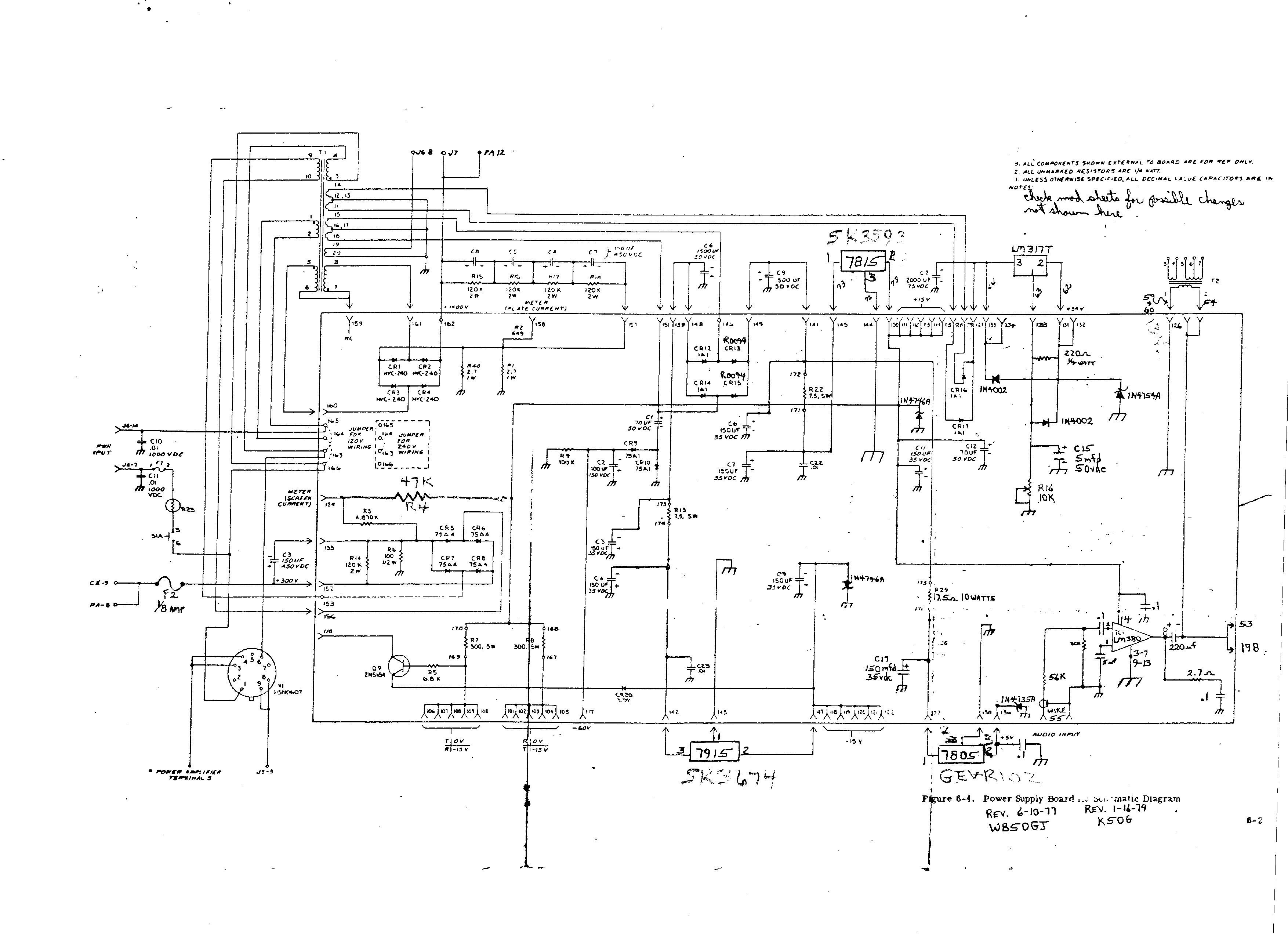
was done by many owners and worked quite well. Here is a schematic that I
created many years ago. It is what I use anytime I make a power supply
mod.
Click this link for the schematic - CX7 Power Supply - IC Mods
There are 3 other iterations of the board and information on them is limited.
I will refer to them by the most accepted name we use to describe them.
The "W2PV Board" required a total rewire of the power supply.
It used a large Molex connector mounted to the board.
Why anyone would have used this board is beyond my capacity to reason.
Installation of this board destroyed the wiring integrity of the radio.
I have removed one of these boards from a CX7. The modification was
abandoned but not before the wiring harness was destroyed.
And I have seen
one other CX7 with
this board that is apparently working.
Here is a link to some information on this modification and other W2PV mods
courtesy of Brian, NI6Q.
W2PV Mods
There is another board that was well built. It used a TO-3 style regulator
mounted to a heat sink on the board for -15 volts.
This is referred to as
the "Johnson Board".
I do not know why. Perhaps it was named after the person who created it.
There is a hand drawn schematic available. It was created by Paul Koller,
W8CXS.
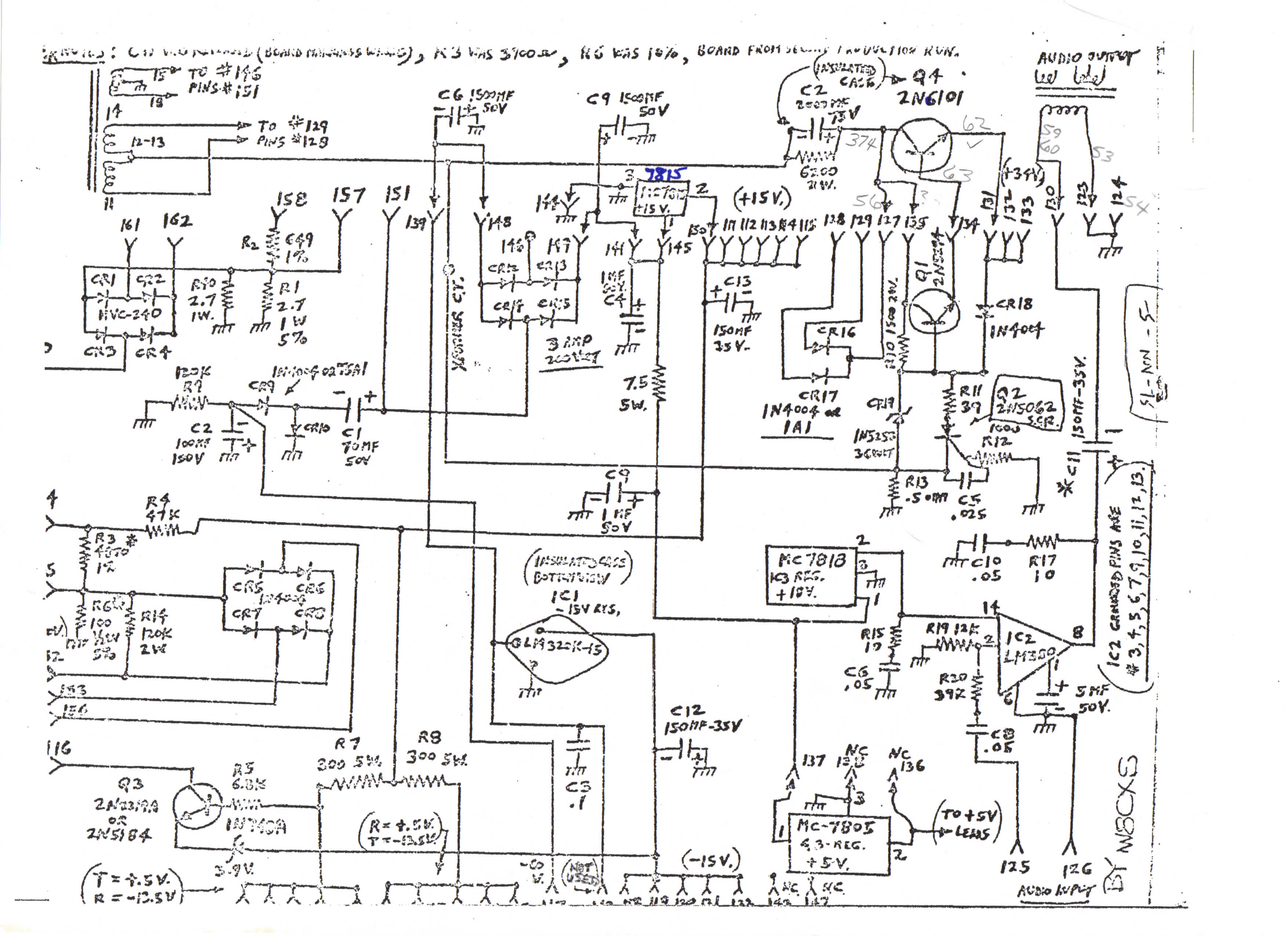
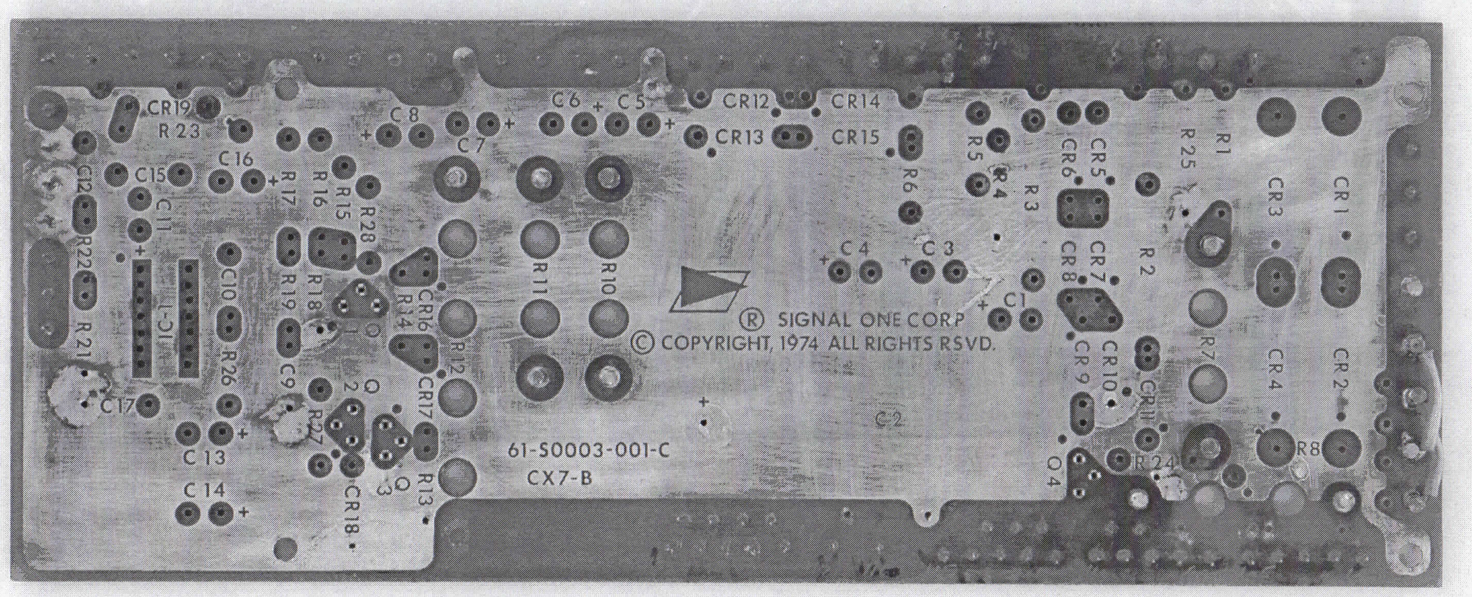
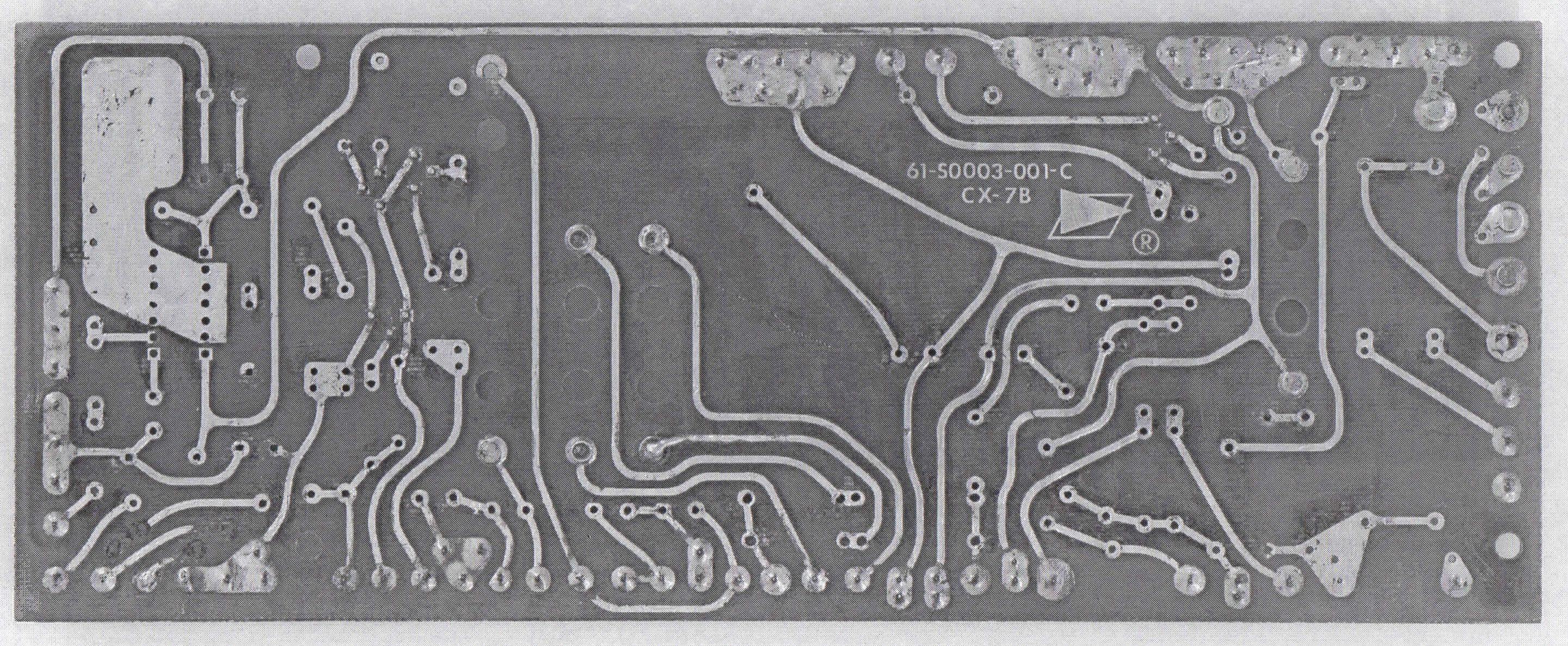
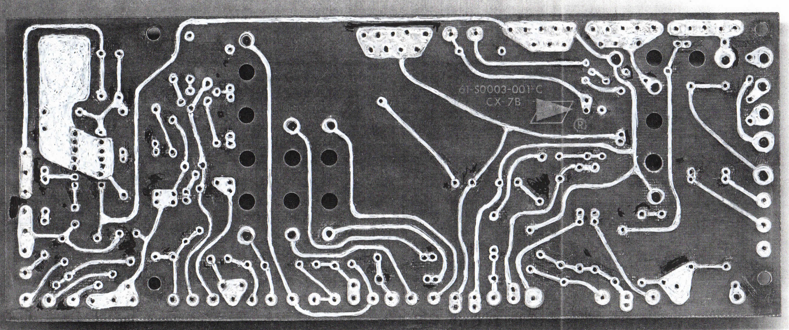
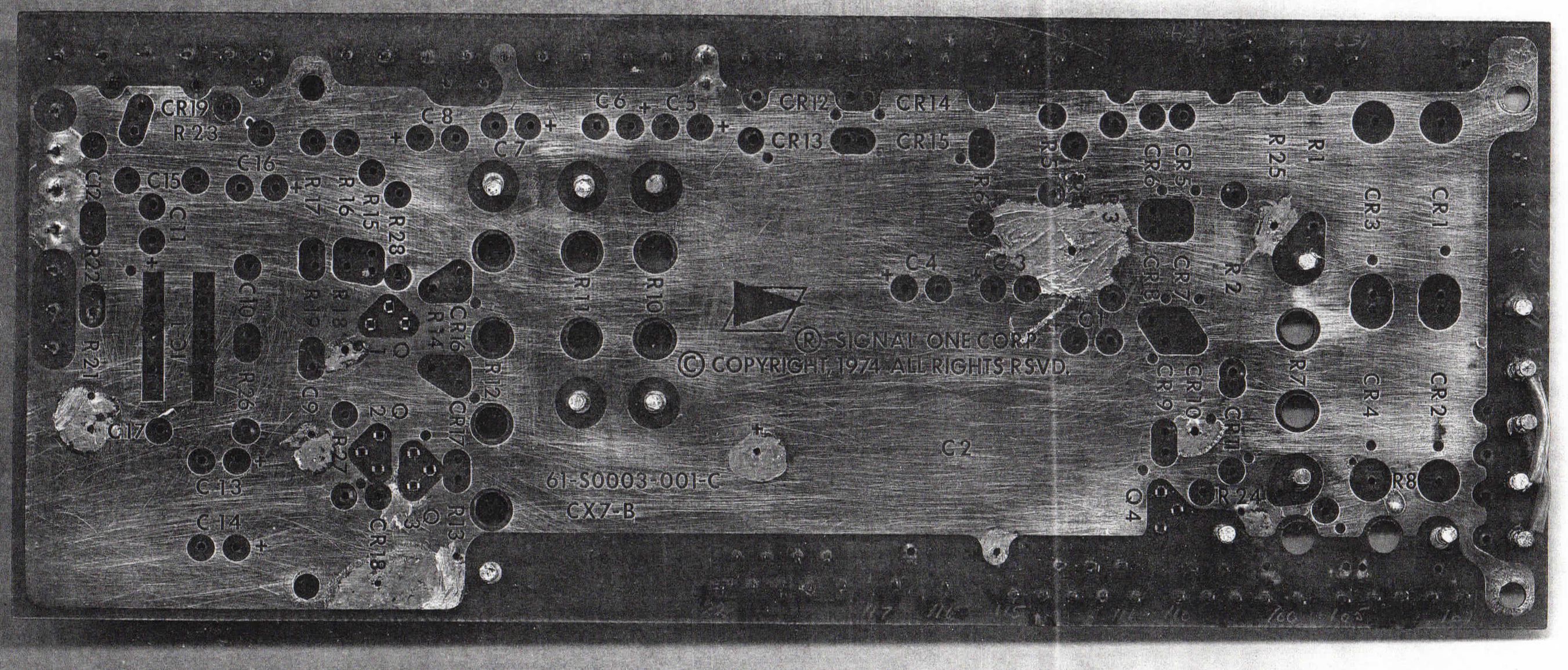
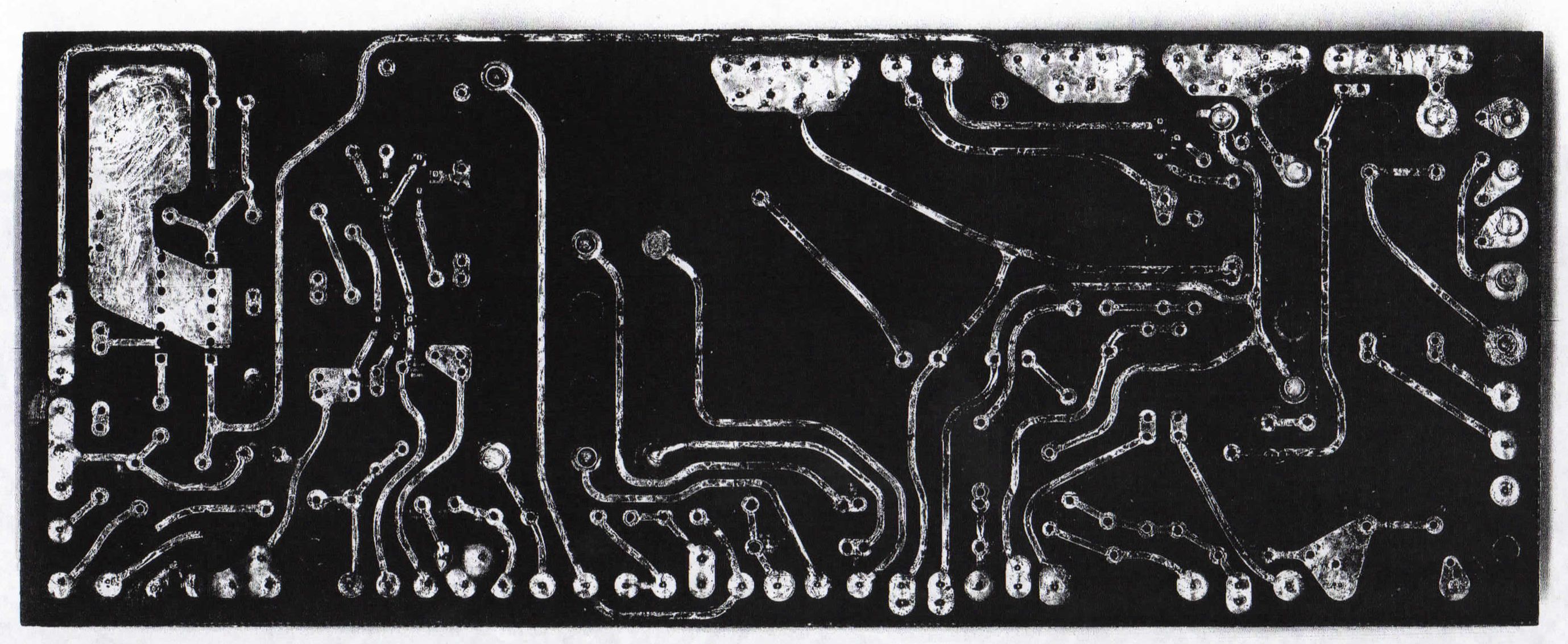
And there was a true Signal/One modification: 61-S0003-001-C.
This board has a copyright date of 1974.
Very late for any CX7 product.
There are several of these boards in CX7s. I have two.
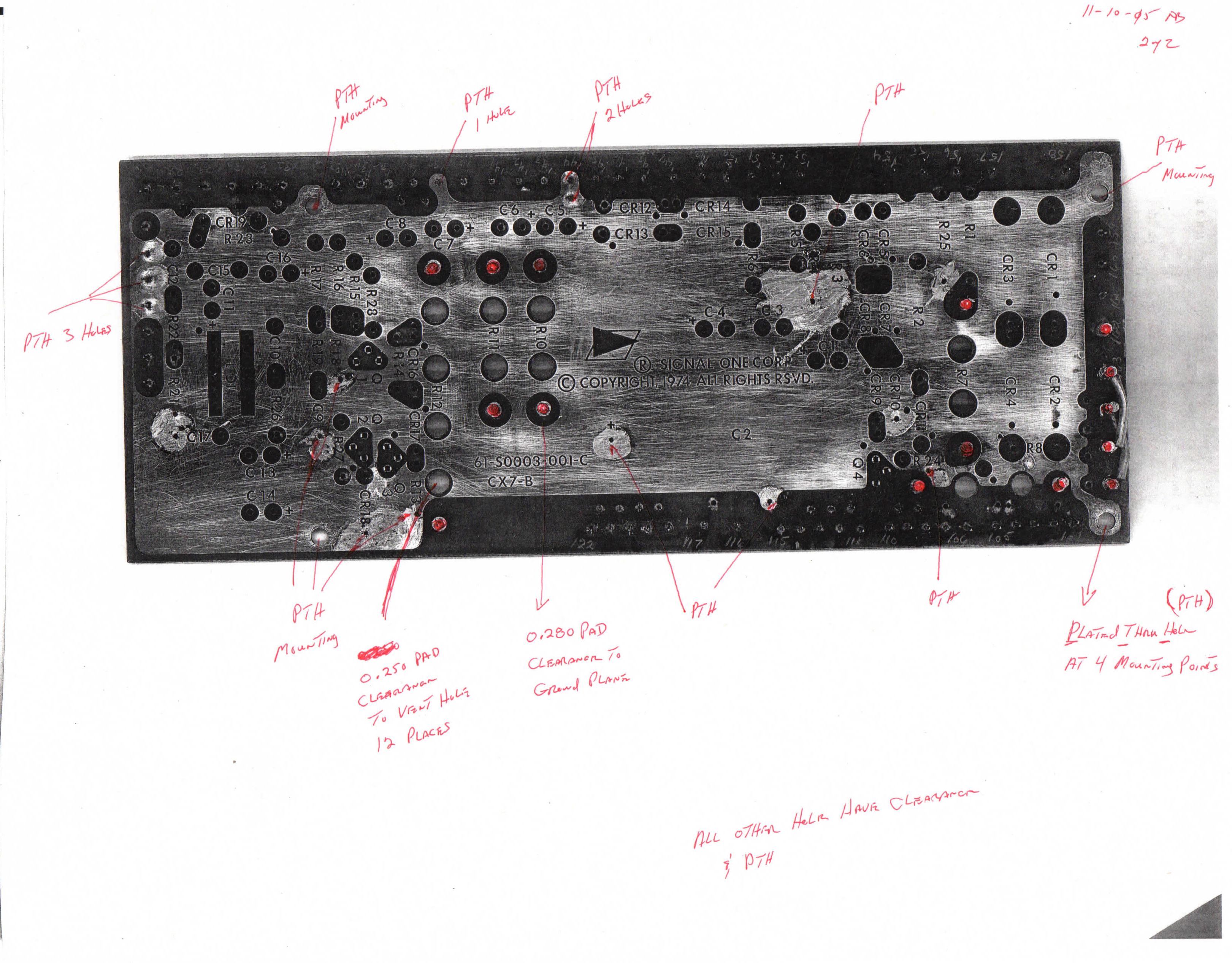
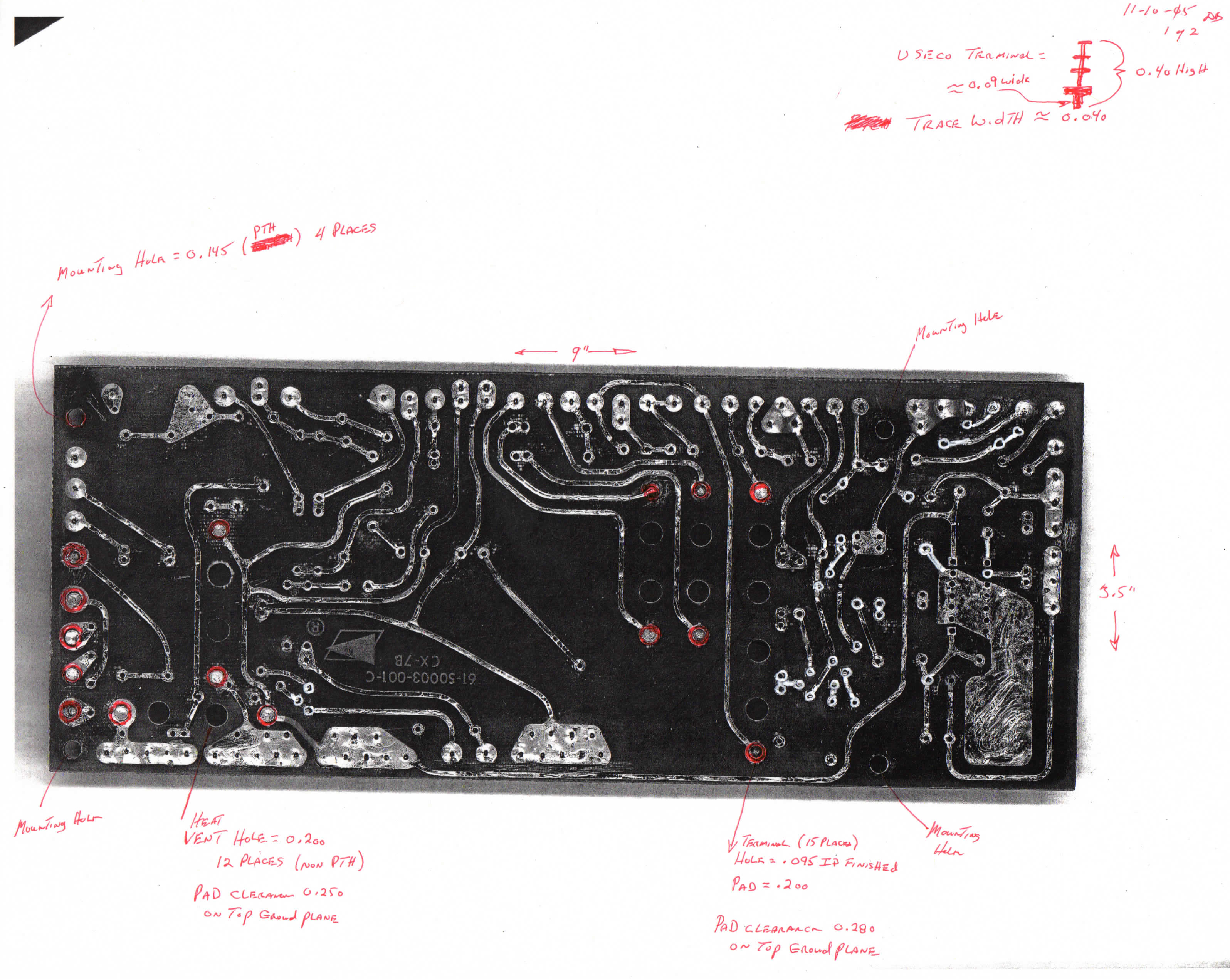
And I just
come across some images of unpopulated boards and notes on several of the pages.
I am not certain who made the notes. There is a schematic in the Signal
One Newsletters- Volume 2, #4.
There are 3 transistors on the board that are used for regulating one of the
voltages.
Gary, W0OGM, and I may attempt to recreate some of these boards. More on
that later.
Here are the pictures of the Revision C Power Supply. Click on thumbnail
for larger image.
![]() Return
to Signal One Info Page
Return
to Signal One Info Page
Created:
October 24, 2019.
Last
Updated: October 24, 2019
Copyright 2017, PakRatz, Corpus Christi, Texas, USA